
4 Pin Relay Wiring Diagram Autok Dpdt Double Pole Double Throw Relay
To wire a 4-pin relay, you need to connect the common pin to the power source, the normally open pin to the device you want to control, and the normally closed pin to the ground or earth. The control pin is connected to a switch or a control module that activates the relay. By using a 4-pin relay, you can safely control high-current devices.
Ημικύκλιο σιλουέτα Καγκουρώ relay pinout Σπανιότητα ηθικό Εθελοντικώς
In this video I show you how to wire a 12 volt automotive Bosch style relay. This video covers both 4 and 5 pin 12VDC relays.Best Connections - 12voltwire.co.
4 Pin Wiring Diagram Cadician's Blog
Control relay wiring diagram example. Consider a 4-pin relay system that allows the dash-mounted light switch (Figure 7 labeled A) to control a high-current load, such as a headlight or fog light (Figure 7 labeled D). The relay acts as an amplifier, allowing a small current from the light switch to control a much larger current to the load..

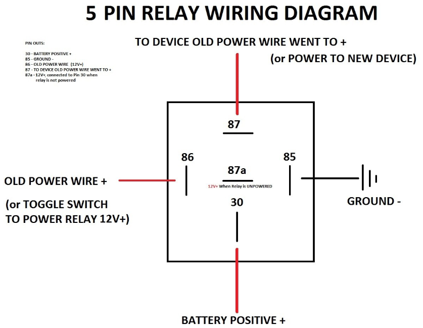
Automotive 5 Pin Relay Diagram
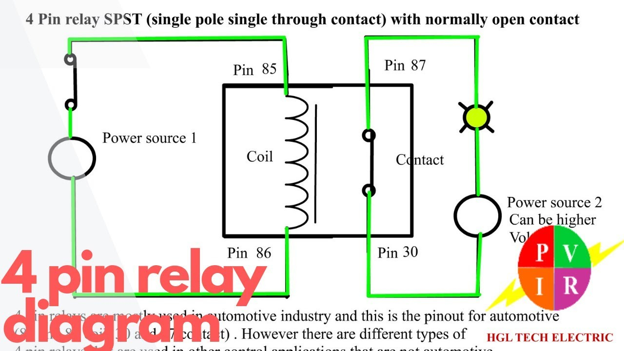
Normally Open (NO) 4-Pin Relay. Both these relays are very similar except that the 4-Pin relay doesn't have the '87a' or the Normally Closed (NC) pin whereas the 5-Pin relay has it. of automotive relays is the positioning of COM pin in the relay. Depending on position of the COM relays are further classified into: Type A Relay.

China 4 Pin Relay Wiring Manufacturers and Suppliers Factory
Relays and wiring can be a real pain, and the whole process of testing and diagnosing can be daunting. If you simplify it and break it into pieces, it's not.

5 Pin Relay Explained / 3 Wire Relay / Undo those taped connections and
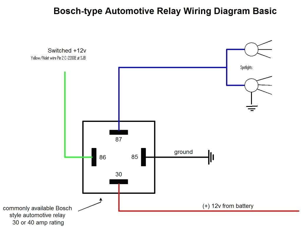
Four-pin relays are commonly used in the application of fog lights, LED lights, and automotive electronics. Wiring a four-pin relay is a simple three-step process: Connect a 12V battery to Pin 30 of the relay via fuse. Connect Pin 85 to the ground.
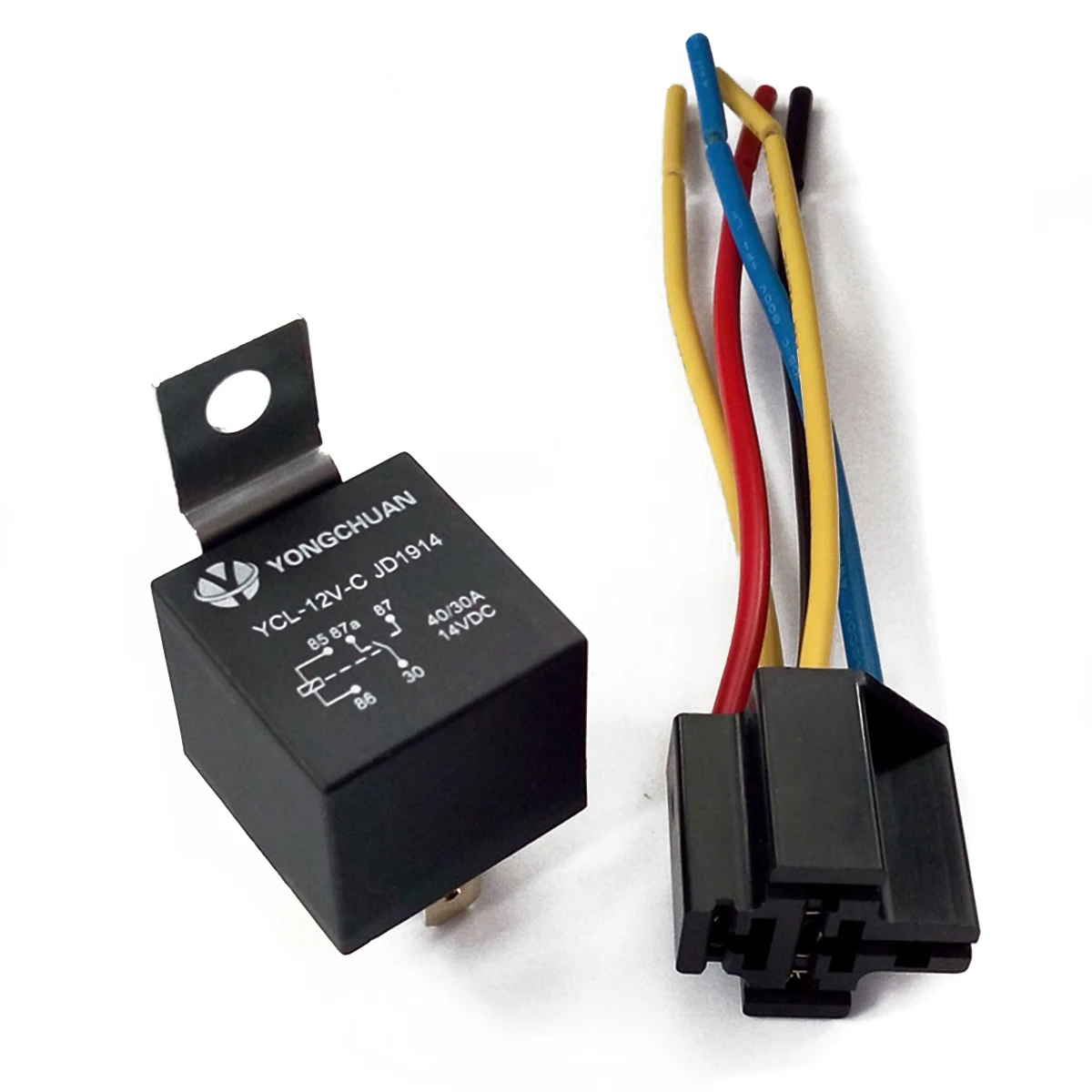
5 Set SPDT 5 Pin 5 Wire Automotive Relay & Socket DC 12V 12 Volt 40A
5-Pin-Relay-Wiring-Diagram-On-Relay-Case. According to DIN 72552 Standard, each pin of a relay is numbered 85, 86, 30, 87, and 87a. You need to know that a relay has two circuits, a coil circuit (also called a "low current circuit", or "inductive circuit"), and a high-amperage circuit. In a relay 85 and 86 pins are considered coil.

4 Pin Relay Connection Diagram Smart Thermostat Wiring
The wiring diagram for a 5-pin relay typically includes all of the same components as a 4-pin relay, plus an additional power source for the control circuit. When wiring a relay, it's important to use proper gauge wire and ensure correct polarity to avoid damage to the relay or other components.

12v 30a Relay 4 Pin Wiring Diagram Wiring Digital and Schematic
No matter what you love, you'll find it here. Search 4 Pin Relay and more. Looking for Great Deals on 4 Pin Relay? From everything to the very thing. All on eBay.

Best Relay Wiring Diagram 5 Pin Wiring Diagram Bosch 5 Pin Relay
Step 2. Connect The Relay's High Amperage Circuit. Similarly, connect a fused wire which comes from the fuse box to the high amperage circuit's terminal 30 of the relay. Connect terminal 87 of the high amperage circuit to the headlight. And you have finished wiring the four-pin relay for light.
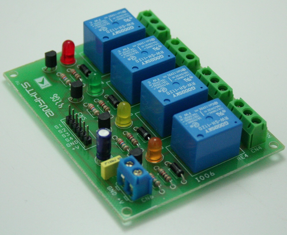
4 Channel Relay Board ElectronicsLab
how to wire a 4 pin relay.Equipment used in the filming is Gopro Hero 8 fromhttp://Gopro.comOthe equipment used for filming is the iSteady gimble fromhttp://.

87a Relay Wiring Diagram Starter
2. Connect the wires: Now connect the negative ground wire to the body ground of the vehicle. Make sure, you make this connection right. Also, keep the positive power red wire away from any moving parts of the engine. We'll connect this one with the relay in the next steps. 3.
44 Luxury 12v 40a Relay Wiring Diagram
By definition, a relay is an electricity-operated switch. It is used in electronic circuits to regulate and control multiple operations. With the help of a relay, you can control a high current circuit via the setup of a low current circuit. Four-pin relays are commonly used in the application of fo.
Remote Relay Wiring Diagram
Wiring 4 Pin Relay: A Comprehensive Guide. A 4-pin relay is a commonly used electrical component that allows you to control a high-current circuit using a low-current signal. It is widely used in automotive applications such as controlling lights, horns, and motors. Understanding how to properly wire a 4-pin relay is essential for anyone.

Other Car Parts Vehicle Parts & Accessories BRAND NEW UNIVERSAL 24 VOLT
A 4-pin relay is an electromechanical switch that controls the flow of current between two circuits. It consists of four terminals: two coil terminals and two switch terminals. The coil is energized when a small current flows through it, activating the switch to allow a larger current to flow in the main circuit.

5 Pin Relay Wiring Diagram Use Of Relay
Quick and easy way to wire a relay to safely power added lights. Why you need a relay is also covered. This video will explain details of how to wire a relay.